Wednesday, July 4, 2012
Flow Measurement -1
EPC-School 2012
I for Instrumentation

 1. Positive Displacement (Quantity Meters) - Some of the more common positive displacement meters are: Weighers, Reciprocating Piston, Rotating Piston, Nutating Disk, Sliding and Rotating Vanes, Gear and Lobed Impeller, and the meter most commonly used to sell small quantities of gas at relatively
low flow rates, the Bellows meter.
2. Inferential (Rate Meters) -
(a) Orifice Plates - The most commonly used rate or inferential meter is the thin-plate, concentric orifice; a detailed discussion is covered in later paragraphs.
(b) Flow Nozzles & Venturi Tubes - Flow Nozzles and Venturi Tubes are primary rate devices which will handle about 60% more flow than an orifice plate for the same bore under the same conditions, and can therefore handle higher velocity flows. If a differential limit is chosen, then a smaller bore nozzle or Venturi may be used to measure the same flow. They are more expensive to install and do not lend themselves to as easy size change or inspection as orifice plates.
(c) Pitot Tubes - A Pitot or impact tube makes use of the difference between the static and kinetic pressures at a single point. A similar device which is in effect a multiple pitot tube, averages the flow profile.
(d) Turbine Meters - A Turbine meter is one in which the primary element is kept in rotation by the linear velocity of the stream in which it is immersed. The number of revolutions the device makes is proportional to the rate of flow.
(e) Swirlmeters, Vortex Shedding Meters, Rotometers, Mass Flow Meters, etc. - These are devices that have applications in flow measurement. The manufacturers should be contacted for detailed information.
What is an Orifice Meter?
An orifice meter is a conduit and a restriction to create a pressure drop. An hour glass is a form of orifice. A nozzle, venturi or thin sharp edged orifice can be used as the flow restriction. In order to use any of these devices for measurement it is necessary to empirically calibrate them. That is, pass a known volume through the meter and note the reading in order to provide a standard for measuring other quantities. Due to the ease of duplicating and the simple construction, the thin sharp edged orifice has been adopted as a standard and extensive calibration work has been done so that it is widely accepted as a standard means of measuring fluids. Provided the standard mechanics of construction are followed no further calibration is required. An orifice in a pipeline is shown in figure 1 with a manometer for measuring the drop in pressure (differential) as the fluid passes thru the orifice. The minimum cross sectional area of the jet is known as the “vena contracta.”
How does it work?
As the fluid approaches the orifice the pressure increases slightly and then drops suddenly as the orifice is passed. It continues to drop until the “vena contracta” is reached and then gradually increases until at approximately 5 to 8 diameters downstream a maximum pressure point is reached that will be lower than the pressure upstream of the orifice. The decrease in pressure as the fluid passes thru the orifice is a result of the increased velocity of the gas passing thru the reduced area of the orifice. When the velocity decreases as the fluid leaves the orifice the pressure increases and tends to return to its original level. All of the pressure loss is not recovered because of friction and turbulence losses in the stream. The pressure drop across the orifice ( P in Fig. 1) increases when the rate of flow increases. When there is no flow there is no differential. The differential pressure is proportional to the square of the velocity, it therefore follows that if all other factors remain constant, then the differential is proportional to the square of the rate of flow.

BETA RATIO is the ratio of orifice plate bore divided by pipe I.D. is referred to as the Beta Ratio or d/D where d is the plate bore and D is the pipe I.D.
THE ORIFICE PLATE
The orifice plate bore can be made in many configurations to handle various flow measurement jobs. The flowing conditions should be checked to see which of the configurations is suitable for each measurement job.
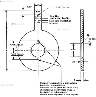
a. The Thin Plate, Concentric Orifice
In the design and use of orifice plates, several basic factors must be followed to assure accurate and reliable measurement. The upstream edge of the orifice must be sharp and square. Minimum plate thickness based on pipe I.D., orifice bore, etc. is standardized. The plate should not depart from flatness along any diameter by more than 0.01 inch per inch of the dam height (D-d)/2. To conform with recommended practices, the orifice-to-pipe diameter ration d/D (called Beta ratio), must not exceed recommended limits.
b. Eccentric Orifice Plates
The eccentric plate has a round opening (bore) tangent to the inside wall of the pipe. This type of plate is most commonly used to measure fluids which carry a small amount of non-abrasive solids, or gases with small amounts of liquid, since with the opening at the bottom of the pipe, the solids and liquids will carry
through, rather than collect at the orifice plate.
c. Segmental Orifice Plates
The opening in a segmental orifice plate is comparable to a partially opened gate valve. This plate is generally used for measuring liquids or gases which carry non-abrasive impurities such as light slurries or exceptionally dirty gases. Predictable accuracy of both the eccentric and segmental plate is not as good as the concentric plate.
d. Quadrant Edge Plate
The quarter-circle or quadrant orifice is used for fluids of high viscosity. The orifice incorporates a rounded edge of definite radius which is a particular function of the orifice diameter.
e. Conic Edge Plate
The conic edge plate has a 45° bevel facing upstream into the flowing stream. It is useful for even lower Reynolds numbers than the quadrant edge.

METER TAP LOCATION
a. Flange Taps
These taps are located one inch from the upstream face of the orifice plate and one inch from the downstream face with a + 1/64 to +1/32 tolerance.
b. Pipe Taps
These taps are located 2½ pipe diameters upstream and 8 pipe diameters downstream (point of maximum pressure recovery). Flange taps are almost universally used in the United States with some older meter stations still using pipe taps.
c. Vena - Contracta Taps
These taps are located one pipe diameter upstream and at the point of minimum pressure downstream (this point is called the vena-contracta). This point, however, varies with the Beta ratio and they are seldom used in other than plant measurement where flows are relatively constant and plates are not changed.
Exact dimensions are given in appropriate tables.
d. Corner Taps
These taps are located immediately adjacent to the plate faces, upstream and downstream. Corner taps are most widely used in Europe, in line sizes less than 2 inches they are used with special honed flow meter tubes for low flow rates.
General Installation Recommendations
1. Meter manifold piping should always be installed to enable calibration as well as to protect the differential
element against overange.
2. The meter should be installed as close as possible to the orifice fitting.
3. Always slope the manifold lines gently from the orifice fitting to the meter to eliminate any high or low
points in the manifold lines.
4. Use condensate chambers or air traps to remove either liquid from a gas system or gas from a liquid
system if lows or highs in the manifold piping cannot be avoided.
It is important when pressurizing or depressurizing differential measuring devices to apply or release pressure to or from the high and low meter chambers uniformly, so as not to impose excessive overange.
Coriolis Mass Flow Meters
Vortex Flow Meters
Ultra Sound Flow Meters
I for Instrumentation
Type of Orifice Plates
low flow rates, the Bellows meter.
2. Inferential (Rate Meters) -
(a) Orifice Plates - The most commonly used rate or inferential meter is the thin-plate, concentric orifice; a detailed discussion is covered in later paragraphs.
(b) Flow Nozzles & Venturi Tubes - Flow Nozzles and Venturi Tubes are primary rate devices which will handle about 60% more flow than an orifice plate for the same bore under the same conditions, and can therefore handle higher velocity flows. If a differential limit is chosen, then a smaller bore nozzle or Venturi may be used to measure the same flow. They are more expensive to install and do not lend themselves to as easy size change or inspection as orifice plates.
(c) Pitot Tubes - A Pitot or impact tube makes use of the difference between the static and kinetic pressures at a single point. A similar device which is in effect a multiple pitot tube, averages the flow profile.
(d) Turbine Meters - A Turbine meter is one in which the primary element is kept in rotation by the linear velocity of the stream in which it is immersed. The number of revolutions the device makes is proportional to the rate of flow.
(e) Swirlmeters, Vortex Shedding Meters, Rotometers, Mass Flow Meters, etc. - These are devices that have applications in flow measurement. The manufacturers should be contacted for detailed information.
What is an Orifice Meter?
An orifice meter is a conduit and a restriction to create a pressure drop. An hour glass is a form of orifice. A nozzle, venturi or thin sharp edged orifice can be used as the flow restriction. In order to use any of these devices for measurement it is necessary to empirically calibrate them. That is, pass a known volume through the meter and note the reading in order to provide a standard for measuring other quantities. Due to the ease of duplicating and the simple construction, the thin sharp edged orifice has been adopted as a standard and extensive calibration work has been done so that it is widely accepted as a standard means of measuring fluids. Provided the standard mechanics of construction are followed no further calibration is required. An orifice in a pipeline is shown in figure 1 with a manometer for measuring the drop in pressure (differential) as the fluid passes thru the orifice. The minimum cross sectional area of the jet is known as the “vena contracta.”
How does it work?
As the fluid approaches the orifice the pressure increases slightly and then drops suddenly as the orifice is passed. It continues to drop until the “vena contracta” is reached and then gradually increases until at approximately 5 to 8 diameters downstream a maximum pressure point is reached that will be lower than the pressure upstream of the orifice. The decrease in pressure as the fluid passes thru the orifice is a result of the increased velocity of the gas passing thru the reduced area of the orifice. When the velocity decreases as the fluid leaves the orifice the pressure increases and tends to return to its original level. All of the pressure loss is not recovered because of friction and turbulence losses in the stream. The pressure drop across the orifice ( P in Fig. 1) increases when the rate of flow increases. When there is no flow there is no differential. The differential pressure is proportional to the square of the velocity, it therefore follows that if all other factors remain constant, then the differential is proportional to the square of the rate of flow.
Vena Contracta and Tapping points
BETA RATIO is the ratio of orifice plate bore divided by pipe I.D. is referred to as the Beta Ratio or d/D where d is the plate bore and D is the pipe I.D.
THE ORIFICE PLATE
The orifice plate bore can be made in many configurations to handle various flow measurement jobs. The flowing conditions should be checked to see which of the configurations is suitable for each measurement job.
a. The Thin Plate, Concentric Orifice
In the design and use of orifice plates, several basic factors must be followed to assure accurate and reliable measurement. The upstream edge of the orifice must be sharp and square. Minimum plate thickness based on pipe I.D., orifice bore, etc. is standardized. The plate should not depart from flatness along any diameter by more than 0.01 inch per inch of the dam height (D-d)/2. To conform with recommended practices, the orifice-to-pipe diameter ration d/D (called Beta ratio), must not exceed recommended limits.
b. Eccentric Orifice Plates
The eccentric plate has a round opening (bore) tangent to the inside wall of the pipe. This type of plate is most commonly used to measure fluids which carry a small amount of non-abrasive solids, or gases with small amounts of liquid, since with the opening at the bottom of the pipe, the solids and liquids will carry
through, rather than collect at the orifice plate.
c. Segmental Orifice Plates
The opening in a segmental orifice plate is comparable to a partially opened gate valve. This plate is generally used for measuring liquids or gases which carry non-abrasive impurities such as light slurries or exceptionally dirty gases. Predictable accuracy of both the eccentric and segmental plate is not as good as the concentric plate.
d. Quadrant Edge Plate
The quarter-circle or quadrant orifice is used for fluids of high viscosity. The orifice incorporates a rounded edge of definite radius which is a particular function of the orifice diameter.
e. Conic Edge Plate
The conic edge plate has a 45° bevel facing upstream into the flowing stream. It is useful for even lower Reynolds numbers than the quadrant edge.
Orifice Plate connected to Diffrential Pressure Transmitter
METER TAP LOCATION
a. Flange Taps
These taps are located one inch from the upstream face of the orifice plate and one inch from the downstream face with a + 1/64 to +1/32 tolerance.
b. Pipe Taps
These taps are located 2½ pipe diameters upstream and 8 pipe diameters downstream (point of maximum pressure recovery). Flange taps are almost universally used in the United States with some older meter stations still using pipe taps.
c. Vena - Contracta Taps
These taps are located one pipe diameter upstream and at the point of minimum pressure downstream (this point is called the vena-contracta). This point, however, varies with the Beta ratio and they are seldom used in other than plant measurement where flows are relatively constant and plates are not changed.
Exact dimensions are given in appropriate tables.
d. Corner Taps
These taps are located immediately adjacent to the plate faces, upstream and downstream. Corner taps are most widely used in Europe, in line sizes less than 2 inches they are used with special honed flow meter tubes for low flow rates.

Orifice Plate Bore and Edge
General Installation Recommendations
1. Meter manifold piping should always be installed to enable calibration as well as to protect the differential
element against overange.
2. The meter should be installed as close as possible to the orifice fitting.
3. Always slope the manifold lines gently from the orifice fitting to the meter to eliminate any high or low
points in the manifold lines.
4. Use condensate chambers or air traps to remove either liquid from a gas system or gas from a liquid
system if lows or highs in the manifold piping cannot be avoided.
It is important when pressurizing or depressurizing differential measuring devices to apply or release pressure to or from the high and low meter chambers uniformly, so as not to impose excessive overange.
Coriolis Mass Flow Meters
Vortex Flow Meters
Ultra Sound Flow Meters
Labels: flow control, flow measurement, flow meters, mass flow, orifice plates, piston, pitot, rotameter, tapping, turbine, vena contracta, venturi, vortex
Comments:
<< Home
Please explian- DIFFERENCE IN METER RUN AND INTEGRAL ORIFICE ASSEMBLY.
# posted by  : July 4, 2012 at 11:26 PM
: July 4, 2012 at 11:26 PM Subscribe to Post Comments [Atom]
<< Home
![]()
Subscribe to Posts [Atom]
Post a Comment
Note: Only a member of this blog may post a comment.